OPTIONAL - print out this web page, check off the steps
as they are completed. They can be checked on the screen instead if desired.
It is recommended to get the latest instructions from the web when building the kit
to insure the latest improvements in the instructions.
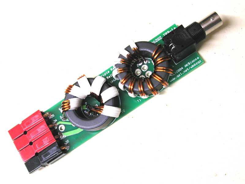
Open the Construction Picture web page in a separate
window to refer to while working with the instructions. Clicking on the link above should
accomplish this. Review the pictures.
Review the parts to insure they are all present.
The list is above.
Prepare a work area with the necessary tools.
I used a wire cutter, Solder station, Solder, Scissors, hemostat (locking pliers),
Xacto knife and a good light.
Locate the 4" piece of #12 bare wire. Set aside the longer piece of #16 enameled wire for the toroid windings.
Cut 4 pieces of #12 bare wire each about 1" in length.
Separate the Anderson Powerpole pins into two piles by size. There are four of the larger diameter 30 amp types that will fit the #12 wire, and two of the smaller diameter 15 amp parts. Set aside the two 15 amp pins together with one red and one black housing for the antenna connections.
Solder a #12 by one inch long wire into each of the four 30 amp Powerpole pins. Clamp the wire vertically. Slide the powerpole pin over the wire. Heat and solder the pin by applying solder to the holes at the top of the tube. Do not get excess solder on the outside of the pin tube or the contact as it will not fit in the housing.
Alternate technique - first crimp the pin to the wire using the Mountain West crimper. Then solder. Other crimpers may or may not work as well.
Snap the soldered #12 wire/pin assemblies into the four powerpole bodies - black, brown, orange and green. The little hook on the end of the contact goes toward the spring inside the housing, clicking over the end of the spring when properly seated.
Bend the wires 90 degrees toward the side with the contact. Grasp the housing with your fingers and the wire with a pair of pliers. Gently bend the wire but do not put too much force on the plastic. The wire should end up just touching the housing and perpendicular to the bottom of the housing toward the contact side. Study the photos.
Join the four powerpole bodies in the order black-brown-orange-green, observing the proper orientation (see photo). From the bottom up, wires facing away from you contacts toward the left, the black body will be the common, the brown 12 ohms, orange 25 ohms and green 50 ohms. Keep in mind the connector will be oriented with the female dovetail side down toward the pc board (contact
tongue side toward PCB).
Note that the brown housing is quite dark and may require good light to differentiate from the black
housing. Refer to the photos.
Fit the powerpole assembly to the PC board on the top (silkscreen) side. The four #12 wires should fit through the holes, and the connectors fit flat against the board. Insure the colors are correct and the connectors are oriented properly and flat against the PC board. Adjust the wires if needed to get a good fit. Review to insure that the black is common, brown 12, orange 25, and green 50 ohms. The impedances are marked on the bottom of the printed circuit board.
Solder the four #12 wires to the PC board. Insure that the connectors stay tight against the top of the circuit board while soldering. Solder one and then check the fit, adjusting if necessary, then solder the rest.
BNC Jack Option - the next two steps will install the
BNC jack. Alternately, the BNC jack can be skipped and coax soldered directly to
the PC Board. If the direct coax option is chosen it is best to complete the board
and then affix the coax to the holes in the center of the bifilar core
using small cable ties and solder the
coax to the pads where the BNC would have been.
Position the BNC jack on the PC board. Insure that it is tight against the board.
Solder the BNC insuring that it stays tight against the board during soldering. Solder one mounting pin first, recheck and adjust, and then solder the rest.
Cut two pieces of #16 enamel wire each 20 inches long. Straighten them and place them side by side with the ends even.
Prepare squares of white fiberglass electrical tape
as needed by cutting with sharp scissors into 1/2" long (by 1/2 inch wide).
Tape the wires together together with approximately 14 each squares of tape. Allow one inch of untaped wire between the taped sections. Start about 1.5" from the end. The purpose of the tape is to hold the wires together to form the 50 ohm transmission line.
The location of the tape is not critical, just keep the wires together.
Wrap the core 12 turns. Observe the photos and compare to the circuit board to insure that the ends will align with the pads for installation. Each pass through the hole in the center of the core counts as a turn.
Prepare the wire ends for soldering by scraping with a sharp Xacto knife or equivalent.
Some prefer to use fine grit sandpaper.
The high quality wire supplied with the kit has thin tough insulation
so it takes a bit of effort to scrape it clear.
The reward is high voltage and tough insulation that will provide
good service in the field.
Insure that the wire is shiny bare.
Do not pre-tin the wire as it may not fit in the circuit board hole.
Stripping completely to bare copper is important for a good solder joint.
Install the core on the PCB and solder. Phase the wires properly by numbering them in a clockwise direction. The first wire in each bundle is the 1-2 wire (one end is 1, the other 2), the second 3-4. On one end, going clockwise, the wires are 1, then 3. On the other end, still going clockwise, the wires are 2 then 4. Refer to
the photos.
Cut 4 pieces of #16 enamel wire each 11 inches long. Straighten them and position them into a side by side configuration with the ends even.
Tape together with 7 each 1" by 1/2" strips of white fiberglass electrical tape with one inch of untaped wire between the taped sections.
Start about 1.5" from the end.
The 1" tape dimension goes around the wire bundle. The
wires form a transmission line, so keep them flat side-by-side and touching.
The purpose of the tape is to hold them flat and touching together while winding
the core.
Wrap the second core six turns.
Prepare the wire ends as before.
Install the core on the PCB and solder. To get the wiring right use the 'clock' and the numbers on the circuit board as above. Remember that the first wire clockwise in the bundle is 1, then 3, 5, and 7. The other end is 2,4,6,8. INSURE THAT THIS TRANSFORMER IS CONNECTED CORRECTLY to the circuit board.
Refer to the photographs and double check the wiring before soldering.
Inspect visually for shorts, poor solder joints, etc.
Repair as needed. Resistance checks don't work on this design since there is a dc
short across the lines. Make it right visually first, then proceed to the RF
checks below.
Test the balun by connecting the BNC end to a 50 ohm load.
A 50 ohm dummy load, resistor, or terminator will do.
Measure the impedances from the antenna end (via the powerpole connectors) using an antenna impedance meter (such as MFJ, Autek or AEA) on 3.5 mhz. It should measure close to 12, 28 and 50 ohms on the appropriate Powerpole connections.
If it does then you have successfully constructed the Triple Ratio Balun!!