Revised for Threaded Valve design March 2010
| These are the instructions for assembling the new model THREADED Pneumatic Antenna Launchers. You can tell if your kit is a threaded kit by the main valve. If it is threaded on the input and output ports then your kit is threaded. For information on assembling the older non-threaded design, see http://www.antennalaunchers.com/csv19/csv19asm.html. | ||
| This is a new document. some parts are not quite complete yet. Use this document with care. If there are any questions contact us and get them resolved before proceeding. | ||
| These instructions are new and as such still in development. Please send any feedback to sales at akbeng dot com. Pictures and video clips will be added as this document matures. Thanks for your patience and help! |
| It is advisable to inventory the Launcher parts both to familiarize you with the parts and to insure that all parts are present. Refer to the packing list and verify that all parts are present. | ||
| Inspect the parts for damage or cracks. Do not use damaged parts - replace any such parts with new undamaged parts before assembling the launcher. |
| PVC Cement and Primer should be used. The type of available cements and primers vary by locale. In our area Purple Primer is required for plumbing code, and this primer insures an excellent cement bond. We recommend using primer. Follow the manufacturer's recommendations for your cement and primer. |
| Always work with cement, primer and paint in an area with adequate ventilation. Read and follow the instructions on the PVC cement, primer and paint. Wear eye protection when building and using the launcher. Do not work near an open flame or other ignition sources. Do not smoke near cement and primer as they are extremely flammable. |
| Insure that the working area has good ventilation. A fan is recommended to blow fresh air on the work area. | ||
| Make sure there is adequate lighting in the work area. | ||
| Make sure that the work surface is protected from the solvent cement and primer. Layers of paper should be spread on the work area. | ||
| Make certain there is no ignition source nearby such as a heater pilot lamp that could ignite the fumes from the primer or cement. | ||
| Protect your good clothes from cement and primer splatter. Either wear old clothes or wear a shopcoat or apron. | ||
| Print out the instructions or set up a computer nearby to use. Insure the computer is out of the range of any primer or cement splatter. |
| Remove any tape and stickers from the PVC especially in the areas that will be cemented or painted such as near the ends of the pipe pieces. Tape or stickers in other locations may be left or removed, it is up to the builder. | ||
| Wash the PVC parts with detergent and warm (not hot) water and rinse well. Pot scrubbers (such as Brillo pads) may be used on the barrel and pressure chamber pipes (but are not recommended for shiny parts such as PVC fittings). | ||
| Make sure that PVC is dry before painting or cementing. |
| This painting section is optional and can be skipped. Painting improves the appearance of the launcher but does not affect functionality. | ||
| PVC can be painted if the proper preparation and paint is used. Krylon Fusion works well. We use Safety Blue for the barrels on pre-assembled launchers. If you choose to paint the Barrel it is best to paint it before assembly. The pressure chamber and U sections are better painted in mid-assembly to prevent the glue from reacting with the paint. | ||
| Mask off the area to be cemented (a bit under 2 inches from one end on the barrel) to prevent painting the surfaces to be cemented. | ||
| Make sure the paint dries according to the manufacturers instructions before handling or cementing the parts. |
| PVC joints are strongest if the PVC Primer is used (and the PVC is clean). In our area the primer is Purple in color. This should be applied according to the manufacturer's instructions. Then cement is applied according to the manufacturer's instructions and the parts are joined and held for a short period of time while the cement 'sets'. Review the Manufacturer's instructions for your PVC cement and primer. | ||
| The thin primer will run and make purple stains, so it pays to think which way the primer will run (downhill) and orient the part so the runs are not a problem. Keep your fingers clean and use absorbent paper on the work surface to catch the drips. |
| In the next steps you will be locating some parts and setting them aside to avoid accidentally using them in the wrong location. Make sure you have identified the parts correctly. |
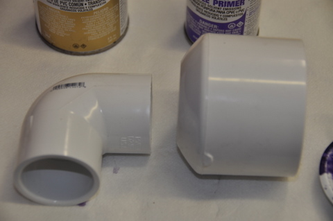
| Locate upper elbow and barrel endcap and set aside - these will be used later. This elbow fits into the bored end of the barrel endcap. |
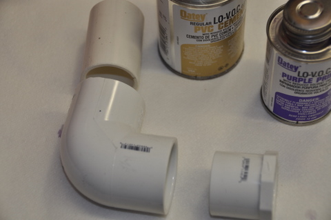
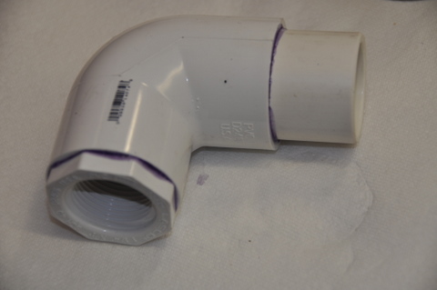
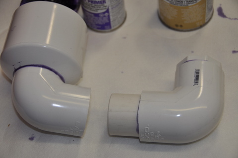
| Locate the Lower Elbow and the Elbow Joiner Pipe and a Threaded Bushing. | ||
| Find the seams on the elbow. One end has two ridges from the casting of the part. These are used to align the elbows when the U is assembled. This is the end the Elbow Joiner Tube is installed in. | ||
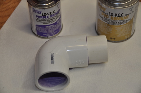
| Prime the inside of the Elbow into both ends. Take care to orient the part so the primer runs downhill inside the elbow and keep the outside of the elbow primer free. | ||
| Prime half of the Elbow Joiner Tube. This half will be installed in the elbow. | ||
| Apply cement inside the elbow on the end with the seams. | ||
| Apply cement to the primed half of the Tube. |
| Seat the Tube into the seamed end of the Elbow and hold it until it sets. | ||
| Prime the outside of the Threaded Bushing. | ||
| Apply cement to the inside of the Elbow's open end. | ||
| Apply cement to the outside of the Bushing. |
| Seat the bushing fully into the Elbow and hold until set. | ||
| Set the elbow assembly aside to dry. |
| Now you have had experience with PVC Solvent Cementing. In the next steps you will be assembling the more critical joints that have continuous pressure when the launcher is pressurized. Leaks in these joints will cause the pressure to fall off until the launch is made, so minimizing this leakage is desirable. Make sure to use PVC primer and sufficient cement on both surfaces to adequately seal the joint. | ||
| The steps will no longer call out the primer and cement application but you should continue to use this recommended procedure for assembly. |
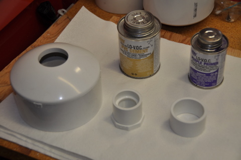
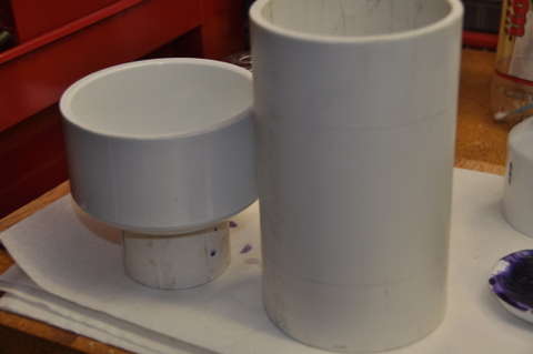
| Locate the pressure chamber rear endcap (with hole), threaded outlet bushing, and bushing support tube. The size of the endcaps varies with different launchers, so the photo may not be exactly the parts you will be using. |
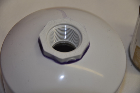
| Install the rear chamber endcap outlet bushing into the bored endcap from the outside. Use PVC primer and cement. |
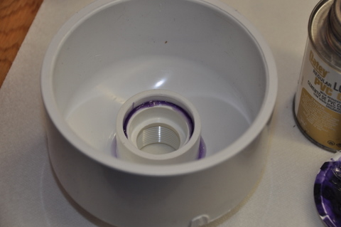
| Install the bushing support tube on the outlet bushing from the inside of the endcap. Use PVC primer and cement. |
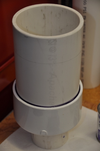
| Locate the pressure chamber pipe and forward endcap. The size of these parts varies with different launchers, so the photo may not be exactly the parts you will be using. | ||
| Draw a pencil line 1-7/8" from each end around the pressure chamber pipe. Use this line to guide the application of primer and cement to the end of the pipe when cementing. |
| Install the pressure chamber pipe to the forward endcap. Use plenty of PVC primer and cement for this large joint. Insure this pipe is fully pushed into the endcap. Hold until set. | ||
| Allow the pressure chamber components to dry for 30 minutes before proceeding to the next step. |
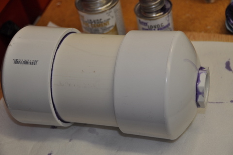
| Install the pressure chamber pipe to the rear endcap. Use plenty of primer and cement for this large joint. This completes the cementing on the pressure chamber. | ||
| Set aside the Pressure Chamber to dry undisturbed for 24 hours. You may continue with other steps below. |
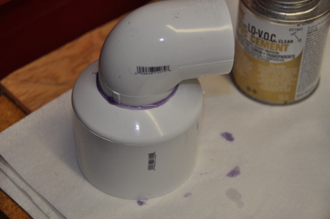
| In this step you will use the upper elbow and barrel endcap set aside earlier... | ||
| Insert the upper elbow into the barrel endcap, pushing it as far as it will go in without forcing it out of square and draw a pencil line on the elbow where the endcap ends to guide the application of primer and cement. | ||
| Remove the barrel endcap. Using a cotton swab apply primer to the elbow next to the line where the endcap will sit. | ||
| Using the cotton swab apply primer to the inside of the barrel endcap where it will sit on the elbow. |
| Apply cement to both the elbow and the endcap areas where they will touch and slide the barrel endcap onto the elbow. Hold until set. |
| Locate the two elbows, the upper with the barrel endcap and the lower with the bushing and elbow joiner pipe. |
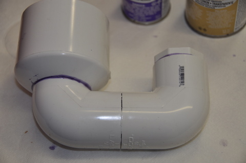
| Join the two elbows into the required "U" shape using cement and primer. This aligns the barrel over the chamber when they are installed later. Line up the seams to align them precisely and push them fully together so the joiner tube is completely inside the elbows. |
| Locate the main valve. It is black with a brass elbow threaded into the valve top and a couple of stainless screws holding the valve top onto the body. | ||
| Remove the screws holding the valve top to the valve body. Set aside the valve top, screws, rubber diaphragm and spring. You will need them later. |
| The trigger strut is an optional part. It provides support for the trigger. Skip the strut steps if not installing it. |
| If you are going to install the trigger strut then drill a hole in the trigger to mount the strut. Otherwise skip this step. The hole is 7/64" in size and located 5/16" from the end of the trigger on the inside side. ... Make sure that the metal from the drilling process does not get into the valve, after drilling shake the crumbs out into a waste basket. |
| If you wish to paint the "U" or chamber sections you may do it now. Insure that the cement has dried for a day before painting. Do not paint the threads. or the interior of the barrel endcap where it will be cemented. | ||
| Insure the paint has dried before proceeding |
| Use the first of the two short threaded PVC pipes. Wrap four turns of teflon tape around the threads on each end. | ||
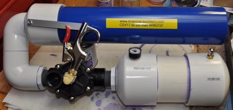
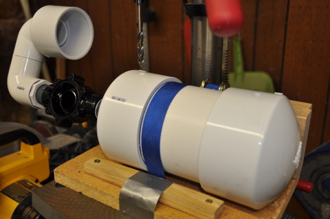
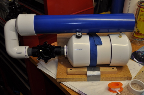
| Turn the pipe into the threaded socket in the 'U' section finger tight. Thread the Main Valve Body onto the other end of the threaded pipe with the flow arrow pointing toward the 'U'. | ||
| Continue turning the Valve Body by hand until the threads are fairly tight and the valve body is oriented as shown in the photo above. The top of the valve should be parallel to the elbows in the "U". |
| Unthread the brass elbow from the valve top. | ||
| Locate the trigger and adapter tube. | ||
| Unthread and remove the flow restrictor from the tip of the trigger, if it is there. Discard this. If the flow restrictor is left on the trigger it will reduce the performance of the launcher. | ||
| Use teflon tape on the adapter tube threads. Thread the trigger to the trigger adapter tube, and the adapter tube to the brass elbow. |
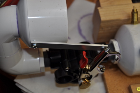
| Tighten until snug and continue until aligned. With your right thumb on the trigger and the trigger outlet upward, the elbow threads should point to the left to put the trigger into the proper orientation. | ||
| Use Teflon Tape on the brass elbow threads. Carefully thread the trigger elbow into the valve top. DO NOT CROSS THREAD. Turn in about 2.5 turns and align as shown, with the trigger over the small filled hole in the valve top. | ||
| **Allow the Pressure Chamber to dry for 24 hours before proceeding to the next step** |
| Appy about four turns of teflon tape to each end of the chamber to valve joiner pipe. | ||
| Thread the joiner pipe into the chamber finger tight. |
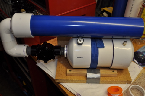
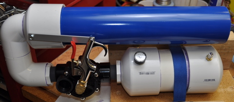
| Thread the valve onto the other end of the joiner pipe. | ||
| Continue tightening until snug. Do not overtighten. |
| Temporarily put the barrel into the barrel endcap part way. Do not make it tight, just insert enough to see where it will go and help choose hole locations in the next step. | ||
| There are two or three locations that will be drilled and tapped. If you have a pressure relief valve to install (in Super kits) it will go into the pressure chamber just behind the barrel. This is the third hole. If there is no relief valve to install there will be only two holes to drill and tap. All holes must be drilled and tapped into the plastic in areas where it is double-thick. This provides more support and depth for the threads. | ||
| All launchers need holes for the pressure gauge near the trigger, and the fill valve near the end of the barrel. |
| Refer to the photo above. Mark the locations for the holes. The holes should be 1.5 inches from the inner ends of the endcaps as shown and clear of the barrel by about an inch. The safety valve should be about 2.5 inches from the gauge hole measured along the curve of the chamber endcap. Placing the holes near the barrel will provide some protection for the gauge and valves. Note the ends of the endcaps are toward the center of the pressure chamber. The holes are drilled away from these ends, in the double thick area of the plastic where the endcap and plastic pipe overlap. | ||
| Drill the holes initially with a 1/8" drill bit and then enlarge them with a 5/16" drill. Make them straight and perpendicular to the chamber tube. A drill press is nice but not required. | ||
| Tap the holes with a 1/8 NPT tap (included in Super kits). Run the tap in only about 2/3 of the way to make the tapered hole tight for a good seal. Using a drop of oil on the tap makes the threads cut a bit cleaner. | ||
| Clean the Pressure Chamber of all bits of PVC. Use a shop vac, compressed air or water rinse to get it clean. Any bits of plastic that remain may foul the valve and make it leak later on. |
| If you are not installing the optional Pressure Safety Relief Valve then skip to the Fill Valve Installation below. | ||
| Apply about 2 wraps of teflon tape to the pressure safety valve threads. | ||
| Carefully thread the pressure safety valve into the hole on the back side of the barrel lining up the threads. Do not cross thread. Use a wrench or deep socket to tighten it until the body just touches the plastic. |
| Apply teflon tape to the threads of the Fill Valve. | ||
| Install the Fill Valve in the threaded hole farthest away from the Main Valve. Make sure to align the threads with the threads in the hole. | ||
| Apply teflon tape to the pressure gauge threads. | ||
| Install the pressure gauge in the threaded hole nearest the trigger. | ||
| Tighten the pressure gauge carefully. Use a thin wrench. Avoid trapping the wrench and damaging the gauge. Align the scale of the gauge as desired when the threads are tight. |
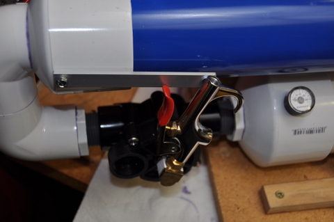
| Place the diaphragm and spring on the Main Valve oriented as shown in the photo. The holes will line up when it is correct. The spring points away from the valve body. |
| Set the valve top in place on the diaphragm oriented so the holes all line up. | ||
| Insert the first screw into one of the holes in the valve top. | ||
| Turn screw backwards gently till it clicks. | ||
| Turn screw gently forward so it follows the existing threads and avoid cutting new threads in the plastic. Tighten till it just touches the plastic | ||
| Repeat for the remaining 5 screws. | ||
| Alternately tighten the six screws until the rubber diaphragm is just slightly squeezed. Do not overtighten. |
| Inspect the Launcher. Look for cracks or other damage. | ||
| If the launcher is damaged it will have to be repaired or destroyed. Do not apply pressure to a damaged launcher. | ||
| Use Safety Glasses and Hearing Protection for the following steps. | ||
| Fill the pressure chamber to 40 psi. | ||
| Wait one minute for the pressure to stabilize and refill to 40 psi if it has dropped. New launchers may initially drop in pressure as the valve seats. | ||
| After 5 minutes read the pressure gauge again. | ||
| If the pressure has dropped more than 5 psi see the Maintenance section of the Launcher Manual on Leaks. | ||
| Increase the pressure to the maximum pressure for the Launcher (80 psi for the CSV19 and 90 psi for the CSV17). | ||
| Allow to sit at maximum pressure for 10 minutes to verify the strength. | ||
| Bleed the pressure down by gently pressing the core of the fill valve. |
| If you are not installing the trigger strut skip to the Install Barrel step below. | ||
| Place the trigger strut screw through one end of the strut, through a strut washer and into the barrel side of the trigger into the hole you drilled earlier. | ||
| Screw the strut screw into the trigger and tighten until it is just shy of being tight. The strut should still move easily. The other end will be attached in a later step. Do not overtighten. |
| Install the barrel into the barrel endcap using PVC primer and cement. To avoid cement damage to the paint prime both parts but use cement only inside the barrel endcap. This is sufficient for this joint. | ||
| Insure that the barrel is fully seated into the endcap. |
| Install trigger strut to barrel (optional) Drill a 7/64" hole in the barrel endcap near the back edge. The strut will be nearly parallel to the barrel. Use a screw through the free end of the strut, then a washer, then into the barrel endcap. Tighten till the strut is just snug. Do not overtighten. |
| On the CSV19 only, install barrel to chamber spacer and strap the barrel to the chamber. |
| Peel the backing from the Label. | ||
| Apply the label to the barrel at the location shown in the photo. |
| NOTE - DO NOT cement the reel mounting tube to the barrel. This is a friction fit for convenient removal during storage and winding operations. | ||
| If you have a Zip Reel or a Mini-Coaxial Reel you may attach it to the barrel. It friction-fits over the end of the barrel. Do not make it tighter than necessary as it may be difficult to remove. It is best to remove the reel while winding the line back on, and when storing the launcher. | ||
| To properly wind the line back onto the Zip or Mini Coaxial Reels, hold the reel in the left hand by the barrel mounting tube. Wind the line with the right hand, reversing the path the line follows when it flows off the reel during launching. DO NOT rotate the reel to wind the line. This will introduce twist. DO NOT wind the line on the reel with too much tension. This may damage the reel. Wind the line with enough tension to hold it in position. Distribute the line over the reel to facilitate smooth feeding during launch. |
| If you have a fishing reel mount, attach the reel foot to the reel mounting tube. Use the supplied hose clamps to hold the foot to the tube as shown in the photo. Best performance is with reels that have large fixed spools such as ocean spinning reels. |
| Launch Ball preparation is shown in the Launcher User's Manual. There is a link below. |
| For further information consult the Pneumatic Launcher User's Manual at www.akbeng.com/w/LauncherManual |